FiddlLink
Choosing a 40G QSFP+ transceiver is a network-design decision, not a simple purchasing task. The correct module must match distance, fiber type, connector design, switch compatibility, and installation conditions. A short data-center link may use 40GBASE-SR4 over multimode fiber. A longer connection may require LR4 optics and single-mode fiber.
Peter Winzer, a respected optical-communications researcher, offers a useful principle: “Optical performance must be evaluated at the system level, not by one specification alone.” That view matters in real installations. A module can support 40Gbps yet fail when its wavelength, power budget, or host interface does not match the network. Check the switch vendor’s compatibility list. Confirm whether the link uses an MPO-12 connector or duplex LC connectors. Inspect the cable polarity before deployment.
Thermal conditions deserve attention, too. A crowded rack can raise module temperature and reduce stability. Digital diagnostics can reveal temperature, voltage, and optical-power changes before an outage occurs. These details are easy to overlook.
Experience also exposes an uncomfortable truth: the cheapest optic is rarely the lowest-cost choice. Replacing mismatched modules, cleaning connectors, or tracing intermittent errors consumes more time than expected. Still, vendor labels are not infallible. Verify specifications against official datasheets and test the complete link whenever possible. This guide explains how to compare 40G QSFP+ transceiver options with practical judgment, technical discipline, and room for reconsideration.
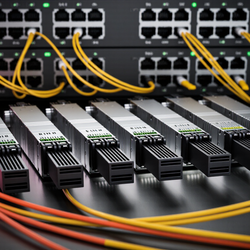
How to Choose a 40G QSFP+ Transceiver?
Understanding 40G QSFP+ transceiver types and standards starts with the link distance. 40GBASE-SR4 uses four multimode optical lanes and an MPO connector. It commonly supports short data-center links, often up to 100 meters with suitable OM3 fiber. 40GBASE-LR4 uses single-mode fiber and duplex LC connectivity. Its four wavelengths are multiplexed into one 40G link, reaching approximately 10 kilometers under standard conditions.
Copper options also deserve attention. 40GBASE-CR4 uses a passive or active direct-attach cable for short rack connections. It reduces optical complexity but adds cable weight and limits placement flexibility. For single-mode deployments, 40GBASE-ER4 can extend reach farther than LR4, though compatibility and power requirements need careful checking. PSM4 is another parallel single-mode option, but it follows a multi-source agreement rather than a traditional IEEE Ethernet designation.
Check the host port standard.
A transceiver must match the switch interface, fiber type, connector, and optical budget. Breakout operation is another practical detail: one 40G QSFP+ port may divide into four 10G links through the correct cable and software configuration. In testing, link failures often come from polarity errors, dirty MPO faces, or unsupported coding. I have also seen specifications treated as universal when they were not. Verify wavelength, lane mapping, temperature range, and digital monitoring requirements before installation. A lower-cost module can become expensive when replacement work interrupts a live rack.
Understanding 40G QSFP+ Transceiver Types and Standards
| Transceiver Type | Standard / MSA | Wavelength | Fiber Interface | Maximum Reach |
|---|---|---|---|---|
| 40GBASE-SR4 on OM3 | IEEE 802.3ba | 850 nm | MPO-12, multimode fiber | 100 m |
| 40GBASE-SR4 on OM4 | IEEE 802.3ba | 850 nm | MPO-12, multimode fiber | 150 m |
| 40GBASE-LR4 | IEEE 802.3ba | 1310 nm CWDM | Duplex LC, single-mode fiber | 10 km |
| 40GBASE-ER4 | IEEE 802.3ba | 1310 nm CWDM | Duplex LC, single-mode fiber | 40 km |
| 40G-PSM4 | PSM4 MSA | 1310 nm | MPO-12, single-mode fiber | 2 km |
| 40G-CWDM4 | CWDM4 MSA | 1310 nm CWDM | Duplex LC, single-mode fiber | 2 km |
Choose the transceiver according to required distance, fiber type, connector, and interoperability standard. SR4 is designed for short multimode-fiber links, while LR4 and ER4 are intended for longer single-mode-fiber connections. PSM4 and CWDM4 are MSA-based options commonly used for 2 km single-mode-fiber links. Reach values represent maximum specified distances under the applicable media and deployment conditions.
Choosing a 40G QSFP+ transceiver starts with the installed fiber, not the port alone. Multimode fiber suits short data center links, often using OM3 or OM4 cable. Single-mode fiber supports longer runs and more demanding campus connections. A typical SR4 module uses four parallel lanes and an MPO connector. A typical LR4 module uses duplex LC connectors over single-mode fiber. Confirm the rated distance carefully. Patch-panel losses, bends, and aging connectors can reduce the real reach. Ten kilometers on a data sheet may not equal ten kilometers in your building.
Connector details deserve equal attention. Check MPO polarity, key orientation, fiber count, and male or female pin configuration. One reversed polarity can leave the link dark. Duplex LC connections also need correct transmit and receive alignment. I have seen technicians replace working optics when the actual fault was a contaminated end face. Cleaning and inspecting connectors should be routine, not an emergency response.
Tips: Match the optic to both fiber type and link length. Check the switch’s supported transceiver specifications before purchasing. Record connector type, polarity, and cable length during installation. A simple label prevents later confusion. I still verify every link with an optical power meter when reliability matters; assumptions are cheaper, but failures are not.
How to Choose a 40G QSFP+ Transceiver?
Checking Device Compatibility and Network Protocol Support
Before choosing a 40G QSFP+ transceiver, check the switch, router, or server documentation carefully. Confirm that the port supports QSFP+ rather than QSFP28 only. A similar connector does not guarantee compatibility. Check the device’s supported transceiver list, electrical specifications, and firmware requirements. Some ports accept only approved module codes. Others support broader multi-vendor operation.
Protocol support matters just as much as physical fit. Verify whether the port uses 40G Ethernet, InfiniBand, or another supported standard. A module designed for one protocol may not establish a link on another. Also check the required lane structure, such as four 10G channels. For short connections, compare multimode fiber requirements and connector type. For longer links, review single-mode fiber support, wavelength, and optical distance.
Read the data sheet closely. Check the operating temperature, power consumption, digital diagnostics, and maximum link budget. In practical installations, mismatched firmware can prevent a link even when the optics appear correct. I have seen technicians replace cables first, while the real problem was unsupported module coding. Testing one module at each end is safer than changing an entire rack. Paper compatibility can still fail. Leave room for that possibility. Record the tested device model, software version, fiber length, and protocol settings for future maintenance.
Optical performance starts with the link budget, not the product label. IEEE 802.3ba defines 40GBASE-SR4 for short multimode links, reaching 100 meters over OM3 and 150 meters over OM4. For longer routes, 40GBASE-LR4 supports up to 10 kilometers over single-mode fiber. In practice, I check connector cleanliness, fiber polarity, and measured receive power before installation. A bright transmitter cannot repair excessive insertion loss.
Reliability needs more than a promised operating temperature. Telcordia GR-468 qualification emphasizes temperature cycling, humidity exposure, vibration, and optical aging. I also prefer modules with digital diagnostics for temperature, voltage, bias current, and received optical power. These readings expose gradual drift before a link fails. Still, diagnostics are not perfect. A stable reading may hide contamination or an intermittent patch-cord fault.
Power use deserves equal attention. The 2024 IEA Electricity report estimates data centers used about 460 TWh globally in 2022, with demand potentially exceeding 1,000 TWh by 2026. A typical 40G QSFP+ module may consume roughly 1.5 to 3.5 watts, depending on design and reach. That difference seems small. In a 1,000-port deployment, it can add several kilowatts continuously, plus cooling overhead. I would compare measured power, not only the datasheet maximum. That lesson is easy to forget.
How to Choose a 40G QSFP+ Transceiver?
Vendor evaluation should begin with evidence, not a low unit price. Request documented compatibility lists, optical specifications, production dates, and failure-rate data. A reliable supplier should explain how each 40G QSFP+ transceiver was tested before shipment. Ask about warranty terms, replacement procedures, and technical support response times. Vague answers create deployment risk.
Testing options should match the real network environment. Check the module on the intended switch, fiber type, and link distance. Measure optical power, receive sensitivity, temperature, and error performance. For critical links, run a traffic test for several hours, not only a quick interface check. Digital monitoring can reveal abnormal temperature or unstable voltage. Test records matter.
Cost extends beyond the transceiver price. Include fiber cleaning, installation labor, power usage, testing time, spare units, and possible service interruptions. A cheaper module may require extra troubleshooting. That difference can exceed its purchase savings. I once underestimated technician travel and replacement delays; the spreadsheet looked accurate, but the project still exceeded budget. This is easy to miss.
Compare total deployment cost across several vendors. Use the same quantities, support assumptions, and replacement rates. Also examine delivery consistency. A delayed shipment can leave expensive network hardware unused. Keep a small reserve for urgent failures, but avoid excessive stock that may age before installation.
Short links commonly use four multimode lanes and an MPO connector.
It suits short connections inside the same rack.
Yes, breakout operation can divide one 40G QSFP+ port into four 10G links.
Check the host port, fiber type, connector, and optical budget.
Confirm whether the port supports 40G Ethernet, InfiniBand, or another required protocol.
Common causes include incorrect polarity, dirty MPO faces, and unsupported coding.
Review temperature cycling, humidity, vibration, and optical aging results.
Typical consumption may range from about 1.5 to 3.5 watts.
Choosing the right 40G QSFP+ transceiver requires more than matching a data rate. Start by understanding the available transceiver types and applicable standards, then confirm whether your network uses single-mode or multimode fiber, the required transmission distance, and the correct connector configuration. These factors directly affect signal quality, installation simplicity, and future network expansion.
Next, verify compatibility with switches, routers, and other optical equipment, including support for the required network protocols and operating conditions. Compare optical performance indicators such as reach, wavelength, temperature range, error performance, and power consumption, while also considering reliability and maintenance needs. Finally, evaluate vendors based on product documentation, testing services, warranty support, and quality consistency. A complete cost assessment should include not only the purchase price, but also installation, testing, power usage, replacement, and long-term management expenses. This balanced approach helps ensure stable performance and a practical total deployment cost.
